LabVIEW无刷直流电机正弦控制查表 点击:376 | 回复:0
LabVIEW无刷直流电机正弦控制查表
该FPGA代码块计算6FET电桥的三个PWM输出,以产生3相正弦电压以驱动无刷直流(BLDC)电机。
描述
控制无刷电机的方法多种多样(6相控制、正弦控制、磁场定向控制等)。最简单的方法是6相控制,涉及根据位置以开/关方式为电机驱动器桥中的6个FET通电。由于电机绕组有6个区域,因此该控制算法中有3个步骤(因此得名)。接下来复杂的BLDC电机控制是正弦或V/f(频率电压或赫兹电压)控制器,它使用三个PWM值来产生近似的三相电流。
该块采用一个输入,该输入表示BLDC电机在0和1023之间的角位置,对应于-pi和pi之间的θ值。该模块的输出是9位(0至511)PWM的三个值。PWM值表示周期为512的PWM中的“导通”时间。
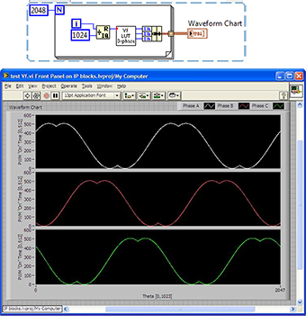
为了实现此控制器,PWM值被发送到6FET桥的每个支路的高边FET。低侧FET总是与高端FET相反的数字值。为了防止击穿,重要的是要延迟PWM信号的上升沿,以考虑FET和电缆动态。将该VI产生的三个FET值发送到专为BLDC控制而设计的电桥,将产生非常接近正弦三相电流的近似值,以驱动BLDC电机。下图显示了两次旋转的PWM值。附件包括产生3个PWM值的VI,测试VI和此处嵌入的图像。

Thisblock of FPGA code computes three PWM outputs for the three legs of a 6-FETbridge to produce a 3-phase sinusoidal voltage to drive a brushless DC (BLDC)motor.
Description
There arevarious ways to control a brushless motor (6-phase control, sinusoidal control,field-oriented control, etc). Thesimplest method, 6-phase control, involves energizing the 6 FETs in the motordriver bridge in an on/off manner dependent on the position. Because there are 6 regions of the motor'swindings, there are six steps in this control algorithm (hence the name). Next in complexity of BLDC motor control isthe sinusoidal or V/f (voltage-over-frequency or voltage-over-hertz) controllerwhich uses three PWM values to generate an approximation of 3-phase current.
The blocktakes an input that represents the angular position of the BLDC motor between 0and 1023 which corresponds to a theta value between -pi and pi. The outputs of the block are three values fora 9-bit (0 to 511) PWM. The PWM valuesrepresent the "on" time in a PWM with a period of 512.
Toimplement this controller, the PWM values get sent to the high-side FETs foreach leg of the 6-FET bridge. Thelow-side FET is always the opposite digital value of the high-side FET. To prevent shoot-through it is important todelay the rising edge of the PWM signal to account for FET and cabledynamics. Sending the three FET valuesgenerated by this VI to a bridge designed for BLDC control will yield a verygood approximation of a sinusoidal, 3-phase current to drive a BLDC motor. The PWM values for two rotations can be seenin the figure below. The attached filesinclude the VI to produce the 3 PWM values, a test VI and the image embeddedhere.
需要说明的是,上述的例程和文档,都是可以下载的,双击即可打开,其中压缩文件是可以采用粘贴复制的方式,拷贝到硬盘上。这不是图片,各位小伙伴看到后尝试一下,这个问题就不用加微信咨询了。有关LabVIEW编程、LabVIEW开发等相关项目,可联系们。附件中的资料这里无法上传,可去公司网站搜索下载。
LabVIEW程序,如下附件所示。
楼主最近还看过
- 工控网中令人厌恶的现象!
 [2669]
 - eplan p8改变导线颜色时有一...
 [9845]
 - PLC常用的几种软继电器
 [2521]
 - 三相异步电动机Y/△换接启动控...
 [2113]
 - 求助:searching local drive...
 [5054]
 - WINCC6.0脚本C语言如何简单地...
 [2563]
 - 紧急求救:使用OMRON SYSMAC-...
 [2312]
 - EPLAN 2022稳定版,解决卡顿问...
 [8757]
 - mcgs6.2产生安装盘的问题
 [2019]
 - 网络培训教程免费下载(mcgs ...
 [3084]

官方公众号

智造工程师
-

 客服
客服

-

 小程序
小程序

-

 公众号
公众号


 工控网智造工程师好文精选
