LabVIEW控制DO通道输出一个精确定时的数字波形 点击:532 | 回复:0

LabVIEW控制DO通道输出一个精确定时的数字波形
如何使用数据采集板卡的DO通道输出一个精确定时的数字波形?
解答:
产生一个数字波形首先需要创建一个布尔数组,把波形序列信息放到该布尔数组中,然后通过一个布尔数组至数字转换vi来产生数字波形。该布尔数组的列数就是数字波形的个数。如果需要对该数字波形的频率进行定时,需要使用计数器输出时钟作为数字波形生成的时钟源,通过该时钟就可以对数字波形精确定时了。
PW = 1 /Freq = Period
可以参考附件中关于生成单数字波形和双数字波形的范例。
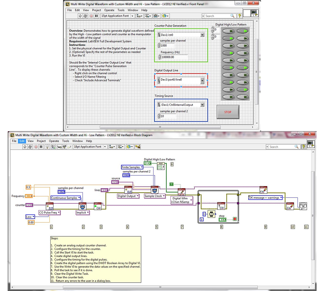
Writea Digital Waveform With a Specific Pulse Width and Digital High/Low Pattern
Overview
Theexample demonstrates how to generate digital waveform defined by the High-Lowpattern control and counter as the width manipulator of the signal (both Singleand Multi works the same)
Description:
Tospecify the pattern of the digital waveform, you must create a boolean arrayand convert it to a digital waveform using the DWDT Boolean Array To Digital.VIThis array will specify the high and low pattern of the digital waveform. Thenumber of columns in the boolean array will correspond to the number of linesthat you are outputting on. Instead of using the internal timebase, use acounter output pulse train as the timing source for the waveform, and this willspecify the pulse width of the digital waveform depending on the frequency ofthe counter pulse train.
Attachedare VIs that will permit one to generate a digital waveform on one line andgenerate a digital waveform on two lines. The block diagrams of each are exactly the same.
The keydifference lies within the controls on the front pannel. Notice in the One_Dig_Wvfrm_Write.vi, thereis only one Digital Output Line; whereas, in the Mult_Dig_Wvfrm_Write.vi, thereare two Digital Output Lines selected. Each column in the Digital High/Low Pattern control corresponds to anindividual digital output line.
Steps toimplement or execute code
Toimplement this example:
Definethe physical channels to be used
(Optional)Set the rest of the parameters as needed
Run theVI
(Optional)Turn on the Highlight Execution to see the flow of the VI
Toexecute this example:
Installthe required software.
Connectthe DAQ hardware that supports the DIO and Counter features
Confirmthe connection with the MAX with TestPanel
Open theVI and refer the Implement Steps
Requirements
Software
LabVIEW2012 or compatible
NI-DAQmx16.0 or compatible
Hardware
cDAQ withC series Digital IO and Counter Module
需要说明的是,上述的例程和文档,都是可以下载的,双击即可打开,其中压缩文件是可以采用粘贴复制的方式,拷贝到硬盘上。这不是图片,各位小伙伴看到后尝试一下,这个问题就不用加微信咨询了。有关LabVIEW编程、LabVIEW开发等相关项目,可联系们。附件中的资料这里无法上传,可去公司网站搜索下载。


楼主最近还看过
- TRACE MODE 6 – 管控一体化整...
 [2041]
 - 求助:关于HoneyWell EBI组态...[2574]
- SolidWorks 2015 MBD—利用三...[2419]
- 请提供节流装置、流量孔板的设...[6551]
- 自动化十八般兵器盘点(下)[2765]
- PLC 输出 NPN与PNP输出电路的...[2113]
- 组态王如何置位离散量[2667]
- 如何打开后缀为EXB的文件[2944]
- WINCC6.0脚本C语言如何简单地...[2563]
- 我能5分钟解除组态王或是mcg...[2481]

官方公众号

智造工程师
-

 客服
客服

-

 小程序
小程序

-

 公众号
公众号


 工控网智造工程师好文精选
